The blueprint is a detailed outline of the topics likely to appear on the lab exam. This blueprint introduces pre-configurations of basic tasks (such as phone registration, basic application integration, basic dial plan, etc.), in order to devote additional focus on expert level skills (advanced configuration and troubleshooting) assessments. As usual, knowledge of troubleshooting is an important skill and candidates are expected to diagnose and solve issues as part of the CCIE lab exam. The topics listed are guidelines and other relevant or related topics may also appear.
1.00
Implement and Troubleshoot Campus Infrastructure and Services
1.01
VLAN
1.02
DHCP
1.03
TFTP
1.04
NTP
2.00
Implement and Troubleshoot CUCM Endpoints
2.01
CUCM SCCP Endpoints
2.02
CUCM SIP Endpoints
3.00
Implement and Troubleshoot CUCME Endpoints
3.01
CUCME SCCP Endpoints
3.02
CUCME SIP Endpoints
4.00
Implement and Troubleshoot Voice Gateways
4.01
T1/E1 PRI
4.02
T1/E1 CAS
4.03
H.323
4.04
MGCP
4.05
SIP
4.06
H.323 RAS
4.07
IP-IP Gateway/CUBE
5.00
Implement and Troubleshoot Call Routing Policies
5.01
Route Patterns and Dial-peers
5.02
Digit Manipulations and Translations
5.03
Class of Services
5.04
Route Selection Preference and Redundancy
5.05
Mobility and Single Number Reach
6.00
Implement and Troubleshoot High Availability Features
6.01
SRST
6.02
AAR
7.00
Implement and Troubleshoot Media Resources
7.01
CODEC Selection and Flexibility
7.02
Conference Bridges
7.03
Transcoder
7.04
Music-on-hold
7.05
Media Resources Preference and Redundancy
7.06
Other CUCM Media Resources
8.00
Implement and Troubleshoot Supplementary Services
8.01
Call Park
8.02
Call Pickup
8.03
Barge
8.04
Callback
8.05
Other Supplementary Services
9.00
Implement and Troubleshoot Other CUCM Voice Applications
9.01
Extension Mobility
9.02
IPMA
9.03
Other CUCM Voice Applications
10.00
Implement and Troubleshoot QoS and CAC
10.01
L2/L3 Traffic Classifications and Policing
10.02
L2/L3 Queuing Mechanisms
10.03
L2 LFI
10.04
RSVP
10.05
Call Admission Control
11.00
Implement and Troubleshoot Messaging
11.01
Cisco Unity Connection
11.02
Cisco Unity Express
11.03
Call Handling and Routing
12.00
Implement and Troubleshoot Cisco Unified Contact Center Express
12.01
Advanced Configuration
12.02
Script Customization
12.03
Redundancy
13.00
Implement and Troubleshoot Cisco Unified Presence
13.01
CUCM Presence
13.02
Cisco Unified Presence Server Integration
2009年9月15日 星期二
CCIE Voice LAB Equipment and Software list
CCIE Voice Lab v3.0 Equipment and Software List
Passing the CCIE Voice Lab Exam requires a depth of understanding difficult to obtain without hands-on experience. Early in your preparation, you should arrange access to the equipment listed below:
Lab Equipment:
Cisco MCS-7845 Media Convergence Servers
Cisco 3825 Series Integrated Services Routers (ISR)
Cisco 2821 Series Integrated Services Routers (ISR)
ISR Modules and Interface Cards+ VWIC2-1MFT-T1/E1 - PVDM2 - HWIC-4ESW-POE - NME-CUE
Cisco Catalyst 3750 Series Switches
IP Phones and Soft Clients
Software Versions
Any major software release which has been generally available for six months is eligible for testing in the CCIE Voice Lab Exam.
Cisco Unified Communications Manager 7.0
Cisco Unified Communications Manager Express 7.0
Cisco Unified Contact Center Express 7.0
Cisco Unified Presence 7.0
Cisco Unity Connection 7.0
All routers use IOS version 12.4T Train.
Cisco Catalyst 3750 Series Switches uses 12.2 Main Train
Network Interfaces
Fast Ethernet
Frame Relay
Telephony Interfaces
T1
E1
2009年9月9日 星期三
CUCM common ports list


Reference:
Full list can be found here
http://www.cisco.com/en/US/docs/voice_ip_comm/cucm/port/7_0/CCM_7.0PortList.pdf
UNITY PIMG Integration
PIMG Integration
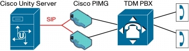
Unity 4.0(4) introduces support for a new device called PIMG (PBX/IP Media Gateway) that takes advantage of the Unity SIP interface. PIMG replaces the voice board as the means for Unity to integrate with legacy PBX systems. Rather than connecting lines from the legacy PBX system to a voice board installed in the Unity server, lines from the legacy PBX system are connected to the PIMG and Unity communicates with the PIMG over the network using SIP. With the PIMG integration, a voice board is no longer installed in the Unity server. Many of the PBX-specific parameters that were previously configured on the Unity server (mostly in the switch file) are now configured on the PIMG, albeit under different headings. As of Unity 4.0(4), one PIMG can support up to eight Unity voice ports. Multiple PIMGs can be configured with Unity to scale to a higher number of voice ports.
PIMG translates call-control commands from the PBX into SIP and sends these SIP messages to Unity. Likewise, PIMG translates SIP messages from Unity into call-control commands that the PBX can understand. Because the PIMG integration relies on Unity's SIP interface, much of the discussion in the previous section about SIP methods, digit generation and detection, and media-format negotiation apply to the PIMG integration as well. One SIP method that is not used with the PIMG integration is REGISTER. PIMG is configured with the IP address of the Unity server, so it knows where to send SIP messages destined for Unity. Because of this, there is no need for Unity to advertise its IP address using REGISTER. Figure 17-29 is an example call flow for a call setup between a phone on the legacy PBX system and Unity, via PIMG.

Notice that the SIP call flow between Unity and PIMG is the same as the call flow shown in the previous section, "SIP Methods used by Unity." Because the PIMG integration is new with Unity 4.0(4), Unity using PIMG does not yet support all of the legacy PBXs that Unity using a voice board can support. However, it is expected that the PIMG integration eventually will allow Unity to communicate with the entire currently supported legacy PBXs. In addition, PIMG opens the door to digital integrations with legacy PBXs that were previously not possible. In general, digital integrations to PBXs are considered more efficient and feature-rich than analog integrations to the same PBX. With PIMG, Unity will eventually support digital integrations to widely deployed PBXs like Nortel Meridian, Avaya Definity, and Siemens HiCom 300, among others. Another benefit of using PIMG with Unity instead of using voice boards is that Unity no longer needs to be collocated with the PBX. This allows for more easily managed systems, where several Unity servers could potentially be located at a central site, and each of these Unity servers could service a different legacy PBX at a remote site.
Reference:
Cisco Unity deployment and solution guide
2009年9月8日 星期二
Troubleshooting Echo Problems between IP Phones and IOS Gateways
Introduction
This document describes how to troubleshoot and eliminate echo where possible in IP Telephony networks with Cisco IOS® gateways.
There are two sources of echo:
-
Hybrid echo
-
Acoustic echo
Hybrid echo is caused by an impedance mismatch in the hybrid circuit, such as a two-wire to four-wire interface. This mismatch causes the Tx signal to appear on the Rx signal.

Acoustic echo is caused by poor acoustic isolation between the earpiece and the microphone in handsets and hands-free devices.

Echo is perceived as annoying when all of these conditions are true:
-
Signal leakage between the analog Tx and Rx paths.
-
Sufficient delay in echo return.
-
Sufficient echo amplitude.
Echo in Packet Voice Networks
The packet segment of the voice connection introduces a significant delay (typically 30 ms in each direction). The introduction of delay causes echoes (from analog tail circuits), that were normally indistinguishable from the side tone, to be now perceived by the user.

The delay introduced by packet voice is unavoidable. Therefore, the voice gateways must prevent the echo. This diagram illustrates how the gateway can reduce the echo before it can enter the packet voice network with the use of an echo canceler.

Refer to Echoed Voice for more information on echo in voice networks.
Prerequisites
Requirements
There are no specific prerequisites for this document.
Components Used
This document is not restricted to specific software and hardware versions.
Conventions
Refer to Cisco Technical Tips Conventions for more information on document conventions.
PSTN Phone User Hears Echo
The problem exists when the PSTN phone user hears echo which is caused by acoustic coupling between the earpiece and the microphone in the IP phone handset.
The solution is to use a load ID on the IP phone, which includes echo suppression on the handset and headset. Currently, available load IDs only include echo cancellation on the speaker phone. However, there are some known issues such as talker echo and acoustic echo from IP phone to IP phone with an older load ID. Refer to Release Notes for Cisco IP CallManager Firmware for 7960, 7940, and 7910 Series Phones if you experience such issues in order to decide if an upgrade to the latest load ID can resolve the issue.

IP Phone User Hears Echo
The problem exists when IP phone users hear echo caused by hybrids in a PSTN network.
The solution is to configure and verify echo cancellation operation on a Cisco IOS gateway. The echo canceler in the voice gateway cancels the echo heard by the IP phone user.

Troubleshoot Echo in Gateways with Cisco IOS Software Releases 12.4
Intermittent echo can be heard on voice gateways that run Cisco IOS Software Release 12.4 with DSPWare 4.4.13 or 4.4.14. This is a known issue documented in Cisco bug ID CSCsd54344 ( registered customers only) . In order to resolve this issue, you need to downgrade DSPware to 4.4.12 or earlier. Contact the Cisco Systems Technical Assistance Center (TAC) in order to obtain assistance in downloading the DSPware image.
Hardware ECAN (MFT-EC-32/MFT-EC-64) on VWIC2-xMFT-T1E1 does not cancel voice echo. This is a known issue documented in Cisco bug ID CSCsb59252 ( registered customers only) .
Troubleshoot Echo Problems with these DSP Voice Quality Metrics
-
Check the delay (DSP/DL) and R-factor (DSP/RF) statistics. You can potentially find perceptible delay between when the originating signal is transmitted and when the echo returns. In most telephones, sidetone helps mask some of the echo. Echos must be delayed by at least 20 milliseconds in order to be perceived.
-
Check the level (DSP/LE) statitstic for sufficient echo amplitude. If the amplitude of the echo is low, it can go unnoticed.
Troubleshoot Echo in Gateways with Cisco IOS Software Releases Prior to 12.2.11T
Cisco IOS Gateway Parameters for when you Troubleshoot Echo
It is important to make sure that the echo canceler has enough information to distinguish between echo and voice conversation. The available parameters to control the distinction are:
-
Input Level—Input gain of a signal is performed before the echo canceler sees the echo.
-
Output Level—Output attenuation of a signal is performed after the echo canceler sees the original output signal.
-
Echo Canceler Coverage—The amount of time the echo canceler remembers a signal that has been output. This parameter must be set to a value greater than the time the echo needs to return to the gateway.

Step-by-step Procedure to Troubleshoot and Eliminate Echo
Complete these steps to eliminate echo.
-
Verify that echo cancellation is enabled on the voice port. Echo cancellation is enabled by default.
Gateway(config-voiceport)#echo-cancel
   coverage   Echo Cancel Coverage
   enable     Echo Cancel Enable
Note: You must shut, then no shut the voice port for the changes to take effect.
Configure the echo canceler coverage to a value greater than the time the echo needs to return to the gateway, so that it is long enough to cover the worst case for your environment, but not longer.
Gateway(config-voiceport)#echo-cancel coverage
   16  16 milliseconds echo canceler coverage
   24  24 milliseconds echo canceler coverage
   32  32 milliseconds echo canceler coverage
   8   8 milliseconds echo canceler coverage
Note: You must shut, then no shut the voice port for the changes to take effect.
Note: The default coverage is set to 8 ms, but you can increase it up to 32 ms. If the PSTN delay (tail length) is more than 32 ms, current echo cancelers in Cisco IOS gateways are not able to cancel the echo. In Cisco IOS Software Release 12.2.13T and later, the echo coverage can be configured up to 64 ms. See the Echo Canceler Enhancements in Cisco IOS releases 12.2.11T and 12.2.13T section of this document.
Measure the echo and adjust the echo signal level as required.
Insufficient echo return loss (ERL) to handle the echo might cause these problems:
Echo canceler does not cancel, but not enough to make echo inaudible.
If the ERL value is too low, the total echo return loss seen by the IP network (ACOM) might be insufficient to suppress the echo. ERL needs to be approximately 20 dB (at least 15 dB).
Note: Acombined (ACOM) is the total echo return loss seen across the incoming and outgoing terminals of the echo canceler (incoming terminal = signal into the ECAN toward the PSTN (voice), and outgoing terminal = signal out of the ECAN toward the IP network (echo)). ACOM is the sum of ERL + ERLE, or the total echo return loss seen by the network.
Note: ACOM (Total loss) = ERL (Tail loss) + ERLE (ECAN loss)
Echo canceler does not cancel.
If the ERL value is too low, the echo signal that returns to the gateway might be too loud (within 6 dB of the talker signal). This causes the echo canceler to consider it as voice (double-talk) instead of echo. As a consequence, the echo canceler does not cancel it. ERL needs to be approximately 6 dB or higher for the echo canceler to engage. In Cisco IOS Software Release 12.2.13T, you can configure this ERL level. See the Echo Canceler Enhancements in Cisco IOS Software Releases 12.2.11T and 12.2.13T section of this document.
In order to prevent these problems, measure the ERL and signal levels. Then adjust the signal levels on the Cisco IOS gateway based on the results. Configure positive values for output attenuation and negative values for input gain to adjust these levels. Input gain is performed before the echo canceler sees the echo signal, and output attenuation is performed after the echo canceler sees the original output signal.
voice-port 1/1:15
   input gain -3
   output attenuation 3
Note: You must shut, then no shut the voice port for the changes to take effect.
Note: In Cisco IOS Software Release 12.2(1) and later, output attenuation can be set to a negative value which actually amplifies the output signal.
Echo can also be caused by an impedance mismatch if both sides are not configured identically. Verify, and modify if needed, the impedance configured in the voice port. A default of 600 ohms is consistent with most lines on the PSTN and PBXs.
Gateway(config-voiceport)#impedance
  600c 600 Ohms complex
  600r 600 Ohms real
  900c 900 Ohms complex
  complex1 complex 1
  complex2 complex 2
Echo Canceler Enhancements in Cisco IOS Software Releases 12.2.11T and 12.2.13T
Echo Suppressor
Enable echo suppressor to reduce the echo during the first two to three seconds of a call, while the echo canceler converges.
Configuration
gateway(config-voiceport)#echo-cancel ?
  coverage    Echo Cancel Coverage
  enable      Echo Cancel Enable
  suppressor  echo suppressor
Software and Hardware Platforms Supported
Echo suppressor is supported in Cisco IOS Software Releases 12.2(11)T, 12.2(12), and 12.2(8)T5. The echo suppressor can only be used on T1 digital signal processors (DSPs) when the default Cisco G.165 EC is used. The echo suppressor cannot be used with the extended EC or on NextPort (Cisco AS5350 and Cisco AS5400) platforms. Except for the extended EC or on NextPort (Cisco AS5350 and Cisco AS5400) platforms, echo suppressor is supported in all platforms and all complexities (c549, c542 and c5409).
Extended Echo Canceler
Configuration
In addition to the default echo canceler used in the Cisco voice gateways (G.165 compliant), a new echo canceler is available in some of the platforms (G.168 compliant). The extended echo canceler provides:
Tail coverage of up to 64 ms.
Enable the extended echo canceler to eliminate the echo when the tail coverage is greater than 32 ms.
Faster convergence.
Enable the extended echo canceler to reduce the echo during the first two to three seconds of a call, while the echo canceler converges. Echo suppressor is not required anymore when you enable the extended echo canceler.
ERL can be tuned.
Enable the extended echo canceler to eliminate the echo when ERL cannot be tuned lower than 6 dBm.
Extended echo cancellation is configured differently based on the version of Cisco IOS software you use. If you use Cisco IOS Software Release 12.3(4)XD or later, you do not have to use any Cisco IOS commands to enable the Enhanced ITU-T standard G.168 Echo Cancellation feature because the extended G.168 EC is the only available echo canceller. You have the option to disable the extended EC, but Cisco highly recommends that you leave it enabled.
The Cisco Enhanced ITU-T G.168 ECAN feature can be run either on the dedicated ECAN modules or the general voice resources that reside on the platform, network module, or advanced integration module. For example, Cisco 2800 Series and 3800 Series integrated services routers can use either the packet voice DSP modules (PVDM2s) mounted in the router chassis or the digital signal processor (DSP) resources on network modules to run the G.168 ECAN feature. When the G.168 ECAN feature is run on general voice resources, processing and memory constraints limit it to have at most 64-ms echo tailcoverage. Although this is adequate in most network conditions, a largerecho tail coverage is sometimes required. In these situations, the dedicated ECAN modules, attached to the appropriate MFT VWIC2, can be used. The processing and memory resources of the dedicated ECAN modules enable the echo canceller to be configured with predefined settings and an extended 128-ms echo tail buffer, which provides robust echo cancellation performance.
Reference:
http://www.cisco.com/en/US/tech/tk652/tk698/technologies_tech_note09186a0080149a1f.shtml
2009年9月7日 星期一
CUCM Extension Mobility
Extension Mobility Configuration Elements
| Configuration Element Name | Configuration Element Function |
| Phone | Stores the configuration of physical phones. Configuration parameters include device-specific phone parameters (such as device CSS, location, or MRGL), user-specific phone parameters (such as user MOH audio source, DND, or softkey template), and (user-specific) button configuration (such as lines or speed dials). |
| End User | The end user is associated with one or more device profiles. The User ID and the PIN are used to log in to a phone with Extension Mobility. |
| Device profile | Stores user-specific phone configuration in logical profiles. Configuration parameters include user-specific phone and button parameters (such as lines and speed dials). The parameters of the device profile are applied to a physical phone after a user logs in to the phone using Extension Mobility. |
| Phone service | Extension Mobility is implemented as a phone service. Hardware phones and device profiles have to be subscribed to the service. |
| Default device profile | Stores the default device configuration parameters that should be applied when the phone model of a user’s device profile is different from the phone model of the phone where the user logs in. |
Relationship Between Extension Mobility Configuration Elements

EM Operation
1. The user presses the Services button on the phone and chooses the Extension Mobility
service from the list of phone services available at the phone.
2. The Extension Mobility service requires the user to log in using his or her user ID and
PIN. The user enters the required data on the phone by pressing each phone button as
many times as needed to select the alphanumeric characters for his or her user ID
and PIN.
3. If the entered user ID and PIN are correct, Extension Mobility chooses the device
profile that is associated with the user.
NOTE If a user is associated with more than one device profile, all associated profiles
are displayed, and the user has to choose the desired profile, as illustrated for User2 in
Figure 12-3. Assigning multiple profiles to a user means that the user is provided with a
separate device profile for each site. Doing this is common when the traditional approach
is used to implement Calling Search Spaces (CSS). Extension Mobility updates only the
line configuration, including the line CSS, but not the device CSS. To allow the choice
of a local gateway for outbound PSTN calls, a different line CSS has to be applied for
each site. In such a scenario, the user chooses a site-specific device profile that differs
from the device profile that is used at other sites in its line CSS. The line CSS of such
site-specific profiles gives access to route patterns that route PSTN calls to the appropri-
ate local gateway to minimize toll charges. Extension Mobility also works well if the
more modern approach of gateway selection of PSTN at the device (phone) level and
blocking the CSS at the line level is implemented.
4. CUCM updates the phone configuration with the settings of the chosen device profile.
User-specific device-level parameters, lines, and other phone buttons are updated with
user-specific settings.
5. The IP Phone is reset and loads the updated configuration.
Extension Mobility Solution to Phone Model Differences
After successful authentication, if the phone model of the device profile does not match the
phone model of the actually used phone, the following happens:
1. Device-dependent parameters such as the phone button template and softkey template
from the default device profile are applied to the phone.
NOTE If the phone button template that is configured in the user's device profile
matches the number of buttons on the login device, the system uses the phone button
template from the user's device profile. Otherwise, the system uses the phone's default
device profile for phone button configuration.
2. The system copies all device-independent configuration settings, such as user hold
audio source, user locale, speed dials, and line configuration, from the device profile to
the login device. Exceptions are the parameters specified under line settings for this
device.
3. The applicable device-dependent parameters of the user's device profile are applied.
These parameters include buttons (such as line and feature buttons) based on the phone
button template that has been applied from the default device profile.
4. If supported on the login device, phone service subscriptions from the user's device
profile are applied to the phone.
5. If the user's device profile does not have phone services configured, the system uses
the phone services that are configured in the default device profile of the login device.
EM Configuration
Step 1 Activate the Cisco Extension Mobility service in CUCM for the cluster.
Step 2 Set Cisco Extension Mobility service parameters.
Step 3 Add the Cisco Extension Mobility phone service.
Step 4 Create default device profiles for all phone models used.
Step 5 Create device profiles, and subscribe them to the Cisco Extension Mobility phone service.
Step 6 Create end users, and associate them with device profiles.
Step 7 Enable Extension Mobility for phones, and subscribe the phones to the Cisco Extension Mobility service.
Reference:
CIPT2 v6.0 Chap12 Implementing Extension Mobility
2009年9月6日 星期日
Erlang Description
![]()
Erlang - a unit of traffic
An Erlang is a unit of telecommunications traffic measurement. Strictly speaking, an Erlang represents the continuous use of one voice path. In practice, it is used to describe the total traffic volume of one hour.
For example, if a group of user made 30 calls in one hour, and each call had an average call duration of 5 minutes, then the number of Erlangs this represents is worked out as follows:
Minutes of traffic in the hour=number of calls x duration
Minutes of traffic in the hour=30 x 5
Minutes of traffic in the hour=150
Hours of traffic in the hour=150 / 60
Hours of traffic in the hour=2.5
Traffic figure=2.5 Erlangs
Erlang traffic measurements are made in order to help telecommunications network designers understand traffic patterns within their voice networks. This is essential if they are to successfully design their network topology and establish the necessary trunk group sizes.
Erlang traffic measurements or estimates can be used to work out how many lines are required between a telephone system and a central office (PSTN exchange lines), or between multiple network locations.
![]()
![]()
Erlang traffic models
Several traffic models exist which share their name with the Erlang unit of traffic. They are formulae which can be used to estimate the number of lines required in a network, or to a central office (PSTN exchange lines). A formula also exists to model queuing situations, and lends itself well to estimating the agent staffing requirements of call centers.
The main Erlang traffic model are listed below, with links to the free online calculators on this Web site:
- Erlang B
This is the most commonly used traffic model, and is used to work out how many lines are required if the traffic figure (in Erlangs) during the busiest hour is known. The model assumes that all blocked calls are immediately cleared. - Extended Erlang B
This model is similar to Erlang B, but takes into account that a percentage of calls are immediately represented to the system if they encounter blocking (a busy signal). The retry percentage can be specified. - Erlang C
This model assumes that all blocked calls stay in the system until they can be handled. This model can be applied to the design of call center staffing arrangements where, if calls cannot be immediately answered, they enter a queue.
![]()
![]()
Further reading
To investigate the traffic unit Erlang, and the Erlang traffic models, we suggest the following sources of information on this Web site:
- Free online Erlang traffic Calculators
These online calculators allow you to perform Erlang traffic calculations now. The Call Minutes Calculator does not even require an understanding of the Erlang traffic unit, and allows entries in minutes rather than Erlangs. Detailed information is available in the Help area (press the Help button). - Dimensioning Trunk Groups
This white paper discusses a method of optimising the number of lines in a trunk group based on the traffic carried by that trunk group. This is known as dimensioning a trunk group, and uses the Erlang B traffic model. - Call Centre Design
This white paper describes the steps involved in assessing the staffing requirements of a call centre and estimating the number of trunks (central office lines) required to serve a call centre for incoming calls. The suggested method uses both Erlang B and Erlang C.
![]()
![]()
A.K. Erlang - a tribute
 Agner Krarup Erlang was born in 1878 in Lønborg, Denmark. He was a pioneer in the study of telecommunications traffic and, through his studies, proposed a formula to calculate the fraction of callers served by a village exchange who would have to wait when attempting to place a call to someone outside the village.
In 1909, he published his first work: The Theory of Probabilities and Telephone Conversations. He gained worldwide recognition for his work, and his formula was accepted for use by the General Post Office in the UK.
Erlang never married. He worked for the Copenhagen Telephone Company for twenty years, until his death in 1929. During the 1940s, the Erlang became the accepted unit of telecommunication traffic measurement, and his formula is still used today in the design of modern telecommunications networks.
Reference:
CUCM deployment and DNS
Network Services
The deployment of an IP Communications system requires the coordinated design of a well structured,
highly available, and resilient network infrastructure as well as an integrated set of network services
including Domain Name System (DNS), Dynamic Host Configuration Protocol (DHCP), Trivial File
Transfer Protocol (TFTP), and Network Time Protocol (NTP).
Domain Name System (DNS)
DNS enables the mapping of host names and network services to IP addresses within a network or
networks. DNS server(s) deployed within a network provide a database that maps network services to
hostnames and, in turn, hostnames to IP addresses. Devices on the network can query the DNS server
and receive IP addresses for other devices in the network, thereby facilitating communication between
network devices.
Complete reliance on a single network service such as DNS can introduce an element of risk when a
critical Unified Communications system is deployed. If the DNS server becomes unavailable and a
network device is relying on that server to provide a hostname-to-IP-address mapping, communication can and will fail. For this reason, in networks requiring high availability, Cisco recommends that you do
not rely on DNS name resolution for any communications between Unified CM and the Unified
Communications endpoints.
For standard deployments, Cisco recommends that you configure Unified CM(s), gateways, and
endpoint devices to use IP addresses rather than hostnames. For endpoint devices, Cisco does not
recommend configuration of DNS parameters such as DNS server addresses, hostnames, and domain
names. During the initial installation of the publisher node in a Unified CM cluster, the publisher will
be referenced in the server table by the hostname you provided for the system. Before installation and
configuration of any subsequent subscribers or the definition of any endpoints, you should change this
server entry to the IP address of the publisher rather than the hostname. Each subscriber added to the
cluster should be defined in this same server table via IP address and not by hostname. Each subscriber
should be added to this server table one device at a time, and there should be no definitions for
non-existent subscribers at any time other than for the new subscriber being installed.
During installation of the publisher and subscriber, Cisco recommend that you do not select the option
to enable DNS unless DNS is specifically required for system management purposes. If DNS is enabled,
Cisco still highly recommend that you do not use DNS names in the configuration of the IP
Communications endpoints, gateways, and Unified CM servers. Even if DNS is enabled on the servers
in the cluster, it is never used for any intra-cluster server-to-server communications and is used only for
communications to devices external to the cluster itself.
Cisco Unified CM 5.0 and later releases do not permit the manual configuration of HOSTS or LHOSTS
files. A local version of the HOSTS table is automatically built by the publisher in each cluster and
distributed to all subscriber nodes via a secure communications channel. This local table is used for
managing secure intra-cluster communications and does not contain addresses or names of any endpoints
other than the Unified CM servers themselves. LMHOSTS files do not exist and are not used by Cisco
Unified CM 5.0 and later releases.
Deploying Unified CM with DNS
There are some situations in which configuring and using DNS might be unavoidable. For example, if
Network Address Translation (NAT) is required for communications between the IP phones and
Unified CM in the IP Communications network, DNS is required to ensure proper mapping of NAT
translated addresses to network host devices. Likewise, some IP telephony disaster recovery network
configurations rely on DNS to ensure proper failover of the network during failure scenarios by mapping
hostnames to secondary backup site IP addresses.
If either of these two situations exists and DNS must be configured, you must deploy DNS servers in a
geographically redundant fashion so that a single DNS server failure will not prevent network
communications between IP telephony devices. By providing DNS server redundancy in the event of a
single DNS server failure, you ensure that devices relying on DNS to communicate on the network can
still receive hostname-to-IP-address mappings from a backup or secondary DNS server.
Hostname resolution within the cluster via either the local HOSTS file or DNS queries is performed only
at subsystem initialization (that is, when a server is booted up). As a result, in order for a server within
the cluster to resolve a DNS name that has been changed in either the HOSTS file or the DNS server,
the Cisco CallManager Service must be restarted on all servers within the cluster.
Reference:
CUCM7 SRND
Troubleshoot Legacy Voice Mail Integration with Cisco CallManager
Introduction
This document troubleshoots the integration of legacy voice messaging systems with Cisco CallManager that utilize Simplified Message Desk Interface (SMDI) and Digital PBX Adaptor (DPA) 7630/7610.
Prerequisites
Requirements
Readers of this document should have knowledge of these topics:
-
Cisco CallManager 3.x or 4.x
-
Telcordia GR 283-core Issue 2 (SMDI)
-
Octel Voice Mail, if applicable (DPA -7630/7610)
Components Used
The information in this document is based on these software and hardware versions:
-
Cisco CallManager 3.x and 4.x
-
Cisco MCS-7835
The information in this document was created from the devices in a specific lab environment. All of the devices used in this document started with a cleared (default) configuration. If your network is live, make sure that you understand the potential impact of any command.
Conventions
Refer to the Cisco Technical Tips Conventions for more information on document conventions.
SMDI Integration with Cisco CallManager
The Cisco Messaging Interface is a service within Cisco CallManager that allows legacy voice mail platforms to connect to Cisco CallManager with the use of SMDI. The Cisco Messaging Interface provides information to a legacy voice mail system about the called and calling party, the reason why the call is presented, and which port the voice mail system should expect the call on. This allows the voice mail system to answer the call correctly.
There are two call types with SMDI:
-
Direct call
-
Forwarded call
Direct Call Format
The direct call SMDI format is:
-
<CR><LF>MDXXXLLLLT<0x20>YYYY<0x20><CR><LF><^Y>
<CR>
Carriage Return
<LF>
Line Feed
MDXXX
Message Desk. This is a 3 digit field, usually 001
LLLL
Logical Terminal Number (0001 ? 4096)
T
Reason Code - D equals Direct Call
<0x20>
Space
YYYY
Calling Party Number
<0x20>
Space
<CR>
Carriage Return
<LF>
Line Feed
<^Y>
End of Medium
This is an example of a direct call from extension 2000. It was presented to the voice messaging system on LTN 0002, or port 2.
-
<CR><LF>MD0010002D<0x20>2000<0x20><CR><LF><^Y>
Troubleshoot a Direct Call
When a caller places a direct call, the caller expects to be prompted to enter their password. In order for that to occur, the gateway, route list and route group to the voice mail system must be configured as Configuring Cisco CallManager 3.0(x) for Integration to Voice Mail Systems via SMDI describes. The most common reason for a direct call to fail is a misconfiguration between either the Message Desk or the Logical Terminal Number (LTN). The Cisco Messaging Interface uses the Message Desk of 001 by default. If you have been given another message desk by either a Private Branch Exchange (PBX) vendor or a central office (CO), you must specify that in the Cisco Messaging Interface configuration.

If the MessageDeskNumber is correct, verify that the LTN is correct. On the Cisco CallManager side, the LTN equates to the ports you configured in the route group. The first port is LTN 1, the second port is LTN 2, and so on. This is why it is essential to configure the Port and Order drop-downs as Configuring Cisco CallManager 3.0(x) for Integration to Voice Mail Systems via SMDI describes. If all ports are chosen, the LTN generated by the Cisco Messaging Interface is LTN 1. This results in failed integration. On the voice mail side, it is essential to ensure that the cabling is correct between the gateway and voice mail ports. Since the SMDI message indicates which port (LTN) the call is being presented to the voice mail system on, all Layer 1 issues have to be resolved.
A second common reason why a direct call to voice mail fails is a misconfiguration of the VoiceMailPartition field in the Cisco Messaging Interface.

The VoiceMailPartition field needs to contain the name of the partition that is assigned to the route pattern that points to the route list for voice mail. If this information is incorrect, the intercept for the VoiceMailDn is not triggered and no SMDI message is generated. Consequently, the voice mail system does not have the proper information to process the call as desired, and answers with a generic greeting.
Verify that the SMDI link is UP on the voice mail side, if your voice mail system relies upon this. Cisco CallManager runs on a standard PC, which means it has nine pins that are actually wired to the serial port. However, Cisco Messaging Interface only uses three of the RS-232 lines: TD, RD, and GND. There are two outbound control lines: RTS and DTR. These are both asserted when the port is opened, but Cisco Messaging Interface does not care if the lines are ignored or not. There are four incoming control lines: DCD, CTS, DSR, and RI. All of these lines are also ignored.
Direct Call Trace from CMI
For troubleshooting issues with SMDI, examine the Cisco Messaging Interface trace files located in the C:/Program Files/Cisco/Trace/CMI directory.
19:27:58.578 Cisco Messaging Interface|   CMISsapiClient::RecvSsCallInfoResMsg()
Received RecvSsCallInfoResMsg userdata = 5996360, Key = 7864, DSL2 = 2,
calledparty =3500, callingparty =2000
19:27:58.578 Cisco Messaging Interface|   CMISsapiClient::RecvSsCallInfoResMsg()
Direct Call port - 2, callingparty -2000
19:27:58.578 Cisco Messaging Interface|-->CMISsapiClient::SendDirectCall()
19:27:58.578 Cisco Messaging Interface|   CMISsapiClient::SendDirectCall()
This is an example of a direct call from extension 2000. It was presented to the voice messaging system on LTN 0002, or port 2.
Send direct call : [<CR><LF>MD0010002D<0x20>2000<0x20><CR><LF><^Y>]
Once you validate that the Cisco Messaging Interface intercepts the VoiceMailDn and generates SMDI messages, you can work with the voice mail vendor to ensure that the message is received. If the voice mail system does not receive any SMDI messages, even though the Cisco Messaging Interface generates them, a PC with hyper terminal can be used to demonstrate whether they leave the Cisco CallManager server.
Forwarded Call Format
Cisco CallManager 3.0 supports the forward reason code of A for All Calls forward. In Cisco CallManager 3.1 and later, the reason codes B and N are added for Busy and No Answer, respectively.
The forwarded call format is:
<CR><LF>MDXXXLLLLTDDDDDDD<0x20>CCCCCCC<0x20><CR><LF><^Y>
<CR>
Carriage Return
<LF>
Line Feed
MDXXX
Message Desk. Number xxx is normally 001
LLLL
Logical Terminal Number (0001 - 4096)
T
Call Type. A is All Calls Forwarded (supported by CM 3.0), B is Busy Forward (CM 3.1), N is for Ring No Answer (CM 3.1)
DDDDDDD
Called Party
<0x20>
Space
CCCCCCC
Calling Party
<0x20>
Space
<CR>
Carriage Return
<LF>
Line Feed
<EM>
End of Medium
This is an example of a forwarded call from extension 2000 to extension 2001. The call is sent to voice mail because the called party's phone is in a Call Forward All state. The call is presented to the voice messaging system on LTN 0002, or port 2.
[<CR><LF>MD0010002A2001<0x20>2000<0x20><CR><LF><^Y>]
Troubleshoot a Forwarded Call
When a caller places a call to another party and is forwarded to voice mail, the expectation is that they receive the called party's greeting. In order for that to occur, gateway to the voice mail system must be configured as described in Configuring Cisco CallManager 3.0(x) for Integration to Voice Mail Systems via SMDI. Ensure that direct calls work before you try to troubleshoot forwarded calls.
When you troubleshoot forwarded calls, check to ensure that the legacy voice mail system supports the forwarded reason code. Some voice mail systems allow for the programming of the various reason codes. In some cases, where the Cisco CallManager was deployed before version 3.1, the voice mail system may not have been programmed to accept the Busy and No Answer forwarded reason code, since Cisco CallManager did not support them at that time.
Forwarded Call Trace from Cisco Messaging Interface
When you troubleshoot issues with SMDI, examine the Cisco Messaging Interface trace files located in the C:/Program Files/Cisco/Trace/CMI directory.
18:33:28.187 Cisco Messaging Interface|   CMISsapiClient::RecvSsCallInfoResMsg()
Received RecvSsCallInfoResMsg fOriginalCdpn = 2001, fCgpn = 2000 fCallingPattern
= 2000
18:33:28.187 Cisco Messaging Interface|   CMISsapiClient::RecvSsCallInfoResMsg()
Received RecvSsCallInfoResMsg userdata = 5996336, Key = 7864, DSL2 = 2,
calledparty = 2001, callingparty = 2000
18:33:28.187 Cisco Messaging Interface|   CMISsapiClient::RecvSsCallInfoResMsg()
Forwarded Call port - 2, calledparty - 2001, callingparty - 2000
18:33:28.187 Cisco Messaging Interface|-->CMISsapiClient::SendCallForwardAll()
18:33:28.187 Cisco Messaging Interface|   CMISsapiClient::SendCallForwardAll()
Send call forward all: [<CR><LF>MD0010002A2001<0x20>2000<0x20><CR><LF><^Y>]
18:33:28.187 Cisco Messaging Interface|-->CMISerialWorker::SendBuffer()
18:33:28.187 Cisco Messaging Interface|   CMISerialWorker::SendBuffer()
Send Buffer - <CR><LF>MD0010002A2001<0x20>2000<0x20><CR><LF><^Y>
18:33:28.197 Cisco Messaging Interface|<--CMISerialWorker::SendBuffer()
18:33:28.197 Cisco Messaging Interface|<--CMISsapiClient::SendCallForwardAll()
This is an example of a forwarded call from extension 2000 to extension 2001. The call is sent to voice mail because the called party's phone is in a Call Forward All state. The call is presented to the voice messaging system on LTN 0002, or port 2.
Once you validate that the Cisco Messaging Interface intercepts the VoiceMailDn and generates SMDI messages, you can work with the voice mail vendor to ensure that the message is received. If the voice mail system does not receive any SMDI messages, even though the Cisco Messaging Interface generates them, a PC with hyper-terminal can be used to demonstrate whether they are leaving the Cisco CallManager server.
MWI Format
The format for message waiting on and off commands is:
MWI On: OP:MWI<0x20>XXXX!<EOT>
OP:MWI
Operate Message Waiting Indicator
<0x20>
Space
XXXX
Extension number
<EOT>
End of Transmission
Example:
OP:MWI<0x20>2001!<EOT>
A request to turn on message waiting for extension 2001.
MWI Off: RMV:MWI<0x20>XXXX!<EOT>
RMV:MWI
Remove Message Waiting Indicator
<0x20>
Space
XXXX
Extension number
<EOT>
End of Transmission
Example:
RMV:MWI<0x20>2001!<EOT>
A request to turn off message waiting for extension 2001.
Troubleshoot MWI
When you troubleshoot MWI issues with SMDI, the first step is determine whether or not the request is received by Cisco CallManager. The Cisco Messaging Interface trace files located at C:/Program Files/Cisco/Trace/CMI reveal whether or not the SMDI message is sent by the voice mail system and received by Cisco CallManager.
If the request is received by the Cisco CallManager, but MWI does not work correctly, verify that the MWI SearchSpace field in the Cisco Messaging Interface contains the partition that belongs to the phone whose lamp is being requested to be turned on/off. The MWISearchSpace field needs to contain the names of the partitions separated by a colon. This field is case sensitive.

MWI Traces from Cisco Messaging Interface
MWI On
18:33:47.846 Cisco Messaging Interface|   CMISerialWorker::SerialThread()
Saw EOT, inbound message: [OP:MWI<0x20>2001!<EOT>]
18:33:47.846 Cisco Messaging Interface|-->CMISsapiClient::OnLampOn()
18:33:47.846 Cisco Messaging Interface|   CMISsapiClient::OnLampOn()
Lamp On - 2001
18:33:47.846 Cisco Messaging Interface|   CMISsapiClient::OnLampOn()
Processed number = 2001
18:33:47.906 Cisco Messaging Interface|<--CMISsapiClient::OnLampOn()
MWI Off
18:33:47.846 Cisco Messaging Interface|   CMISerialWorker::SerialThread()
Saw EOT, inbound message: [RMV:MWI<0x20>2001!<EOT>]
18:33:47.846 Cisco Messaging Interface|-->CMISsapiClient::OnLampOff()
18:33:47.846 Cisco Messaging Interface|   CMISsapiClient::OnLampOff()
Lamp Off - 2001
18:33:47.846 Cisco Messaging Interface|   CMISsapiClient::OnLampOff()
Processed number = 2001
18:33:47.906 Cisco Messaging Interface|<--CMISsapiClient::OnLampOff()
Known Issues
FXS ports on the 6624 blade and AT-x gateway do not go on-hook in a timely manner.
The default behavior of these devices is to go on-hook when they receive reorder tone. However, many voice mail systems do not disconnect on reorder, but rather dialtone. You can modify the Call Restart Timer from its default value of 5000 to 1234 in order to change the behavior of the gateway.

Error messages about the Cisco Messaging Interface in event viewer.
Error:  CMyProcessConfigList::GetSafeIntegerParam() catch
handler Parameter MessageDeskNumber not found in database, using
default value of 1.
In early releases of Cisco CallManager, the Message Desk parameter was hard coded to 1. In Cisco CallManager 3.0(7), support for configurable Message Desk numbers was introduced. If you do not define a Message Desk Number, Cisco CallManager uses Message Desk 1.
Cisco Messaging Interface does not stay running.
With the release of Cisco CallManager 3.0(7), the VoiceMailDn field is required.
No MWI with Octel 250/350 when Octel uses multiple SMDI links.
When Octel voice mail systems use multiple SMDI links, it is necessary to specify over which link the MWI command needs to be sent. In the mailbox profile, you can edit the Int. Link Number field to correspond to the SMDI link that connects the Octel to the Cisco CallManager.
Cisco DPA 7630/7610
The Cisco DPA 76xx Voice Mail Gateway is a VoIP gateway that enables legacy voice mail equipment to connect to a Cisco IP Telephony solution network. The Cisco DPA 7610 allows Octel voice mail systems that currently use Digital Station Emulation to connect to a Nortel Meridian 1 PBX, to instead connect to a Cisco IP CallManager system. The Cisco DPA 7630 allows Octel voice mail systems that currently use Digital Station Emulation to connect to an Avaya Definity PBX, to instead connect to a Cisco IP CallManager system without any changes to the voice mail system.
The Cisco CallManager views the Cisco DPA 76xx as a collection of 30 VIP phones and the PBX's Avaya G3 views the DPA as a collection of 7504D digital phones. The Nortel Meridian M1 views the DPA as a collection of 2616 phone sets.
Troubleshoot Calls to Voice Mail through a Cisco DPA 7630/7610
The Cisco DPA 76xx gateways have very precise wiring requirements. It is essential to verify cabling when you troubleshoot issues with the Cisco DPA76xx.
You can find the Cisco DPA 7630 requirements in Connecting to the Octel and Definity Systems on a Cisco DPA 7630.
You can find the the Cisco DPA 7610 requirements in Connecting to the Octel and Meridian 1 Systems on a Cisco DPA 7610.
Once you are certain that the Layer 1 issues are resolved, you can investigate these suggestions.
Symptom: Reorder tone is played out to the caller when a call is placed to voice mail.
Suggestion: If the DPA is configured beyond twelve ports, the thirteenth caller can receive reorder if the first twelve ports are in use. Cisco CallManager has a service parameter titled ForwardMaximumHopCount. By default, this field is set to a value of 12.

Set this value to the number of ports configured on the DPA.
Symptom: Callers get the main greeting (open trees) rather than the greeting for the subscriber's mailbox.
Suggestion: The DPA relies upon the value entered into the Cisco CallManager 'Pilot' directory number field for deployments of more than one DPA. The CallManager 'Pilot' directory number should be the first port of the first DPA. While the first DPA knows the directory numbers (DNs) associated with its own ports, subsequent DPAs need this information to ensure correct integration.
Note: The most common misconfiguration is when a customer configures a CTI route point or a hunt group that forwards to the DPA. This is not necessary, as you can simply assign the appropriate DN to the first DPA port.
Troubleshoot MWI with a Cisco DPA 7630/7610
In order for message waiting notification to work correctly, Cisco CallManager and the DPA must be configured to use the same DNs for MWI.

The values that are entered under Service > Service parameters > Cisco CallManager, for MessageWaitingOn DN and MessageWaitingOffDN must match the values entered in the DPA under Configure > CallManager.

Symptom: MWIs do not turn on or off.
Suggestion: Ensure that the MWI on/off DNs are not part of a more generic pattern. For example, check that there is not a route pattern of 1xxx that points to a gateway.
Symptom: MWIs do not turn off on the Octel 250/350 platform.
Suggestion: For MWIs to function properly, the Message Waiting Timeout feature in menu 6.2, In-Band Integration of the Octel system must be set to the 1 - Timeout = Positive Acknowledgment setting. The 2 - Timeout = Negative Acknowledgment setting directs the Octel system to interpret the lack of a confirmation tone as an error indication. The DPA 7630/7610 requires that the 1 - Timeout = Positive Acknowledgment option be used.
Symptom: With the Cisco DPA 7630, MWIs do not turn on or off.
Suggestion: The Avaya G3 PBX makes use of feature codes to set message waiting on the PBX. The Octel voice mail system consequently uses them also. These are traditionally *4 and #4 for Leave Word Calling Activate and Cancel, respectively. On the Octel 250/350 platform, in menu 6.2, In-Band Integration, there are two parameters: Dialing Sequence to Activate MWI and Dialing Sequence to Deactivate MWI. These values should be the same as those configured in the DPA under Configure > Octel/Definity integration.

For one reason or another, many Octel systems have the Dialing Sequence to Activate MWI and Dialing Sequence to Deactivate MWI configured as *4PN and #4PN, rather than simply *4N and #4N. The P represents a pause, usually of 500 ms, and this delay can cause issues with MWI before DPA code 1.2(1).
Reference:
http://www.cisco.com/en/US/products/sw/voicesw/ps556/products_tech_note09186a00800a8956.shtml#format
Troubleshooting EM_PARK Issues for E&M Digital CAS Signaling
Introduction
In digital E&M signaling on Cisco 2600, 3600, and MC3810 router platforms, some T1/E1 time slots can get stuck in the EM_PARK state. This is visible when you issue the show voice call summary command. This document explains how to troubleshoot this issue.
This output shows that some time slots are in the EM_PARK state. A time slot in the EM_PARK state is not used for voice calls.
Router#show voice call summary
PORT      CODEC     VAD    VTSP STATE     VPM STATE
=====     ======    ===    ==========     ==========
1/0:0.1     -        -          -         EM_ONHOOK
1/0:0.2     -        -          -         EM_PARK
1/0:0.3     -        -          -         EM_PARK
1/0:0.4     -        -          -         EM_ONHOOK
1/0:0.5     -        -          -         EM_ONHOOK
Prerequisites
Requirements
There are no specific requirements for this document.
Components Used
The information in this document is based on these software and hardware versions:
Hardware—Cisco 2600, Cisco 3600, Cisco VG200, and MC3810 routers
Software—All
The information in this document was created from the devices in a specific lab environment. All of the devices used in this document started with a cleared (default) configuration. If your network is live, make sure that you understand the potential impact of any command.
Background Theory
In T1 CAS, for example, wink start signaling, when the PBX goes offhook, the router/gateway side time slot remains in the idle (EM_ONHOOK) state until the call is answered by a remote destination. The router time slot state changes to EM_OFFHOOK when the call is answered by the remote destination.
If the call does not connect, the router/gateway plays the inband reorder tones to the caller. Since the channel state on the router side is still EM_ONHOOK, the router is unable to hang up the channel. After the caller hangs up, the PBX needs to change its channel state from offhook to onhook.
In some cases, the PBXs do not send the onhook messages, with the help of the ABCD transitions. The router has a workaround for this called fake answer. Without the fake answer workaround, the channels hang in a state of EM_PARK indefinitely. See the Fake Answer section for more information.
Note: Calls can be stuck in the EM_PARK state on some T1 channels if the voice gateway router chasis is not electrically grounded properly. Refer to the hardware installation guide for more information about electrical grounding.
Conventions
Refer to Cisco Technical Tips Conventions for more information on document conventions.
Problem
There are two possible, major reasons that the time slot is stuck in the EM_PARK state:
The digital signal processor (DSP) is bad and has either hardware or software issues.
The PSTN switch/PBX sends a continuous offhook signal to the router and does not release it.
Solution
These are the solutions to this problem:
If the time slots in your system are stuck in the EM_PARK state, check the DSPs. Refer to Troubleshooting the DSP on NM-HDV for Cisco 2600/3600 Series Routers in order to check the DSPs.
If the DSPs are alive, the problem can be on the PSTN switch/PBX side or the Cisco IOS® (router/gateway does not start the Fake Answer procedure). See the Fake Answer section for more information.
Fake Answer
The Cisco router/gateway waits for a default value of 30 seconds (use the timeouts wait-release and timeouts call-disconnect commands in order to change these values) after it knows that the time slot needs to be set from the PBX to onhook while it plays the reorder tone.
If this does not happen, the router moves the time slot to the EM_PARK state and starts another timer with a duration of 10 seconds. If the PBX still does not go onhook after the 10-second duration, the router tricks the PBX. The router sends a fake answer of a one second duration and then goes onhook.
After the router sends the fake answer signal, the router starts another timer of five minutes. If the PBX goes onhook, the timer stops and the router transitions the time slot to the EM_ONHOOK state. Otherwise, after five minutes it sends another fake answer signal of a one-second duration. The router repeats this process until the PBX goes onhook. The router forces the PBX to clear the call.
Note: This answering transition is not updated to any accounting record since the actual call is cleared. But, the PBX understands it as an answer and the user is probably charged for the one-second duration call.
If the DSP associated with the time slot in the EM_PARK state is alive and healthy and the problem persists, run the debug vpm all and debug vtsp all commands in order to see if Cisco IOS attempts to send the fake answer.
Note: You need to run the debugs for more than five minutes.
Note: In most cases, if the DSP is bad, the router does not perform the fake answer workaround. Refer to Troubleshooting the DSP on NM-HDV for Cisco 2600/3600 Series Routers for more information.
This debug output shows how a time slot becomes stuck in EM_PARK and how the fake answer workaround works.
Jan 11 17:19:00.767: htsp_dsp_message: SEND/RESP_SIG_STATUS: state=0xC timestamp
=44262 systime=31305235
Jan 11 17:19:00.767: htsp_process_event:
[4/1:1(10), EM_ONHOOK, E_DSP_SIG_1100]em_onhook_offhook htsp_setup_ind

!--- Offhook signal is received from the switch.

Jan 11 17:19:00.767: [4/1:1(10)] get_local_station_id calling num= calling name=
calling time=01/11 17:19
Jan 11 17:19:00.767: vtsp_tsp_call_setup_ind (sdb=0x62BB7B14, tdm_info=0x0, tsp_
info=0x62BB4050, calling_number= calling_oct3 = 0x0, called_number= called_oct3
= 0x81, oct3a=0x0): peer_tag=0
Jan 11 17:19:00.767: : ev.clg.clir is 0
ev.clg.clid_transparent is
0
ev.clg.null_orig_clg is 1
ev.clg.calling_translated is false

Jan 11 17:19:00.767: htsp_timer - 3000 msec
Jan 11 17:19:00.767: vtsp_do_call_setup_ind
Jan 11 17:19:00.767: vtsp_allocate_cdb,cdb 0x62DCEA70
Jan 11 17:19:00.767: vtsp_do_call_setup_ind: Call ID=112722, guid=62DC4230
Jan 11 17:19:00.767: vtsp_do_call_setup_ind: type=0, under_spec=1640890368,
name=, id0=10, id1=1, id2=25038, calling=, called= subscriber=RegularLine
Jan 11 17:19:00.767: vtsp_do_normal_call_setup_ind
Jan 11 17:19:00.771: cc_api_call_setup_ind (vdbPtr=0x62BB7FA0,
callInfo={called=
,called_oct3=0x81,calling=,calling_oct3=0x0,calling_oct3a=0x0,calling_xlated=fal
se,subscriber_type_str=RegularLine,fdest=0,peer_tag=0, prog_ind=3},callID=0x62DC
40DC)
Jan 11 17:19:00.771: cc_api_call_setup_ind type 1 , prot 0
Jan 11 17:19:00.771: vtsp_insert_cdb,cdb 0x62DCEA70
Jan 11 17:19:00.771: vtsp_open_voice_and_set_params
Jan 11 17:19:00.771: dsp_close_voice_channel: [4/1:1:32995] packet_len=8 channel
_id=3 packet_id=75
Jan 11 17:19:00.771: dsp_open_voice_channel_20: [4/1:1:32995]
packet_len=16 channel_id=3 packet_id=74 alaw_ulaw_select=0
associated_signaling_channel=130 time_slot=2 serial_port=0
Jan 11 17:19:00.771: vtsp_modem_proto_from_cdb: cap_modem_proto 1073741824
Jan 11 17:19:00.771: vtsp_modem_proto_from_cdb: cap_modem_proto 1073741824
Jan 11 17:19:00.771: dsp_encap_config: [4/1:1:32995] packet_len=30 channel_id=3
packet_id=92
TransportProtocol 2 t_ssrc=0x0 r_ssrc=0x0 t_vpxcc=0x0 r_vpxcc=0x0
sid_support=1, tse_payload=65535, seq_num=0x0, redundancy=0
Jan 11 17:19:00.771: dsp_set_playout_delay
Jan 11 17:19:00.771: dsp_set_playout: [4/1:1:32995] packet_len=18 channel_id=3 p
acket_id=76 mode=1 initial=60 min=40 max=200 fax_nom=300
dsp_set_playout_delay_config
Jan 11 17:19:00.771: dsp_set_playout_config
Jan 11 17:19:00.771: mode 0, init 60, min 40, max 200 playout default
Jan 11 17:19:00.771: dsp_set_playout_config:mode 0, init 60, min 40, max 200
Jan 11 17:19:00.771: dsp_set_playout_config: [4/1:1:32995] packet_len=18 channel
_id=3 packet_id=76 mode=1 initial=60 min=40 max=200 fax_nom=300
Jan 11 17:19:00.771: dsp_echo_canceler_control: echo_cancel: 1
Jan 11 17:19:00.771: dsp_echo_canceler_control: [4/1:1:32995] echo_cancel 1,
disable_hpf 0, flags=0x0, threshold=-21
Jan 11 17:19:00.771: dsp_echo_canceler_control: [4/1:1:32995] packet_len=12
channel_id=3 packet_id=66 flags=0x0, threshold=-21
Jan 11 17:19:00.771: set_gains: FXx/E&M: msg->message.set_codec_gains.out_gain=0
Jan 11 17:19:00.771: dsp_set_gains: [4/1:1:32995] packet_len=12 channel_id=3
packet_id=91 in_gain=0 out_gain=0
Jan 11 17:19:00.771: dsp_vad_enable: [4/1:1:32995] enable: packet_len=12 channel
_id=3 packet_id=78 thresh=-38
Jan 11 17:19:00.771: cc_process_call_setup_ind (event=0x62E63ACC)
Jan 11 17:19:00.771: >>>>CCAPI handed cid 32995 with tag 0 to app "DEFAULT"
Jan 11 17:19:00.771: sess_appl: ev(24=CC_EV_CALL_SETUP_IND), cid(32995), disp(0)
Jan 11 17:19:00.771: sess_appl: ev(SSA_EV_CALL_SETUP_IND), cid(32995), disp(0)
Jan 11 17:19:00.771: ssaCallSetupInd
Jan 11 17:19:00.771: ccCallSetContext (callID=0x80E3, context=0x62DFBCF0)
Jan 11 17:19:00.771: ssaCallSetupInd cid(32995),
 st(SSA_CS_MAPPING),oldst(0), ev
(24)ev->e.evCallSetupInd.nCallInfo.finalDestFlag = 0
Jan 11 17:19:00.771: ccCallSetupAck (callID=0x80E3)
Jan 11 17:19:00.771: ccGenerateTone (callID=0x80E3 tone=8)
Jan 11 17:19:00.771: ccCallReportDigits (callID=0x80E3, enable=0x1)
Jan 11 17:19:00.771: vtsp_report_digit_control: enable=1:
digit reporting enabled
Jan 11 17:19:00.771: cc_api_call_report_digits_done (vdbPtr=0x62BB7FA0,
callID=0x80E3, disp=0)
Jan 11 17:19:00.771: : vtsp_get_digit_timeouts
Jan 11 17:19:00.771: sess_appl: ev(52=CC_EV_CALL_REPORT_DIGITS_DONE),
cid(32995), disp(0)
Jan 11 17:19:00.771: cid(32995)st(SSA_CS_MAPPING)ev
(SSA_EV_CALL_REPORT_DIGITS_DONE)
oldst(SSA_CS_MAPPING)cfid(-1)csize(0)in(1)fDest(0)
Jan 11 17:19:00.771: ssaReportDigitsDone cid(32995) peer list: (empty)
Jan 11 17:19:00.771: ssaReportDigitsDone callid=32995 Enable succeeded
Jan 11 17:19:00.771: ccGenerateTone (callID=0x80E3 tone=8)
Jan 11 17:19:00.771: vtsp:[4/1:1:32995, S_SETUP_INDICATED, E_CC_SETUP_ACK]
Jan 11 17:19:00.775: act_setup_ind_ack
Jan 11 17:19:00.775: vtsp_modem_proto_from_cdb: cap_modem_proto 0
Jan 11 17:19:00.775: vtsp_modem_proto_from_cdb: cap_modem_proto 0
Jan 11 17:19:00.775: dsp_encap_config: [4/1:1:32995] packet_len=30 channel_id=3
packet_id=92 TransportProtocol 2 t_ssrc=0x0 r_ssrc=0x0 t_vpxcc=0x0 r_vpxcc=0x0
sid_support=1, tse_payload=65535, seq_num=0x0, redundancy=0
Jan 11 17:19:00.775: dsp_voice_mode: [4/1:1:32995] cdb 62DCEA70,
cdb->codec_params.modem 2, inband_detect flags 0x21
Jan 11 17:19:00.775: map_dtmf_relay_type--digit relay mode: 2
Jan 11 17:19:00.775: dsp_voice_mode: [4/1:1:32995] packet_len=24 channel_id=3
packet_id=73 coding_type=1 voice_field_size=160 VAD_flag=0
echo_length=256 comfort
_noise=1 inband_detect=33 digit_relay_mode=2
AGC_flag=0act_setup_ind_ack: modem_mode = 0, fax_relay_on = 1
Jan 11 17:19:00.775: act_setup_ind_ack(): dsp_dtmf_mode()
 dsp_dtmf_mode(VTSP_TONE_DTMF_MODE)

Jan 11 17:19:00.775: dsp_dtmf_mode: [4/1:1:32995] packet_len=10 channel_id=3
packet_id=65 dtmf_or_mf=0
Jan 11 17:19:00.775: vtsp_timer: 31305236
Jan 11 17:19:00.775: vtsp:[4/1:1:32995, S_DIGIT_COLLECT, E_CC_GEN_TONE]
Jan 11 17:19:00.775: act_gen_tone
Jan 11 17:19:00.775: dsp_cp_tone_off: [4/1:1:32995] packet_len=8 channel_id=3
packet_id=71
Jan 11 17:19:00.775: dsp_cp_tone_on: [4/1:1:32995] packet_len=38 channel_id=3
packet_id=72 tone_id=4 n_freq=2 freq_of_first=350 freq_of_second=440
amp_of_first=5514 amp_of_second=5514 direction=1 on_time_first=65535
off_time_first=0 on_time_second=0 off_time_second=0
Jan 11 17:19:00.775: vtsp:[4/1:1:32995, S_DIGIT_COLLECT, E_CC_GEN_TONE]
Jan 11 17:19:00.775: act_gen_tone
Jan 11 17:19:00.775: dsp_cp_tone_off: [4/1:1:32995] packet_len=8 channel_id=3
packet_id=71
Jan 11 17:19:00.775: dsp_cp_tone_on: [4/1:1:32995] packet_len=38 channel_id=3
packet_id=72 tone_id=4 n_freq=2 freq_of_first=350 freq_of_second=440
amp_of_first=
5514 amp_of_second=5514 direction=1 on_time_first=65535 off_time_first=0
on_time4_second=0 off_time_second=0
Jan 11 17:19:00.775: htsp_process_event: [4/1:1(10), EM_WAIT_SETUP_ACK,
E_HTSP_SETUP_ACK]em_wait_setup_ack_get_ack
Jan 11 17:19:00.775: htsp_timer_stop
Jan 11 17:19:00.775: htsp_timer2 - 172 msec
Jan 11 17:19:00.947: htsp_process_event: [4/1:1(10), EM_WAIT_SETUP_ACK,
E_HTSP_EVENT_TIMER2]em_wait_prewink_timer
Jan 11 17:19:00.947: em_offhook (0)[recEive and transMit4/1:1(10)] set signal st
ate = 0x8em_onhook (200)[recEive and transMit4/1:1(10)] set signal state = 0x0

!--- A wink of duration 200 msec is sent out to the switch.

Jan 11 17:19:01.471: vtsp_process_dsp_message: MSG_TX_DTMF_DIGIT_BEGIN: digit=9,
rtp_timestamp=0xED31C493

Jan 11 17:19:01.471: vtsp:[4/1:1:32995, S_DIGIT_COLLECT, E_DSP_DTMF_DIGIT_BEGIN]
Jan 11 17:19:01.471: act_report_digit_begin
Jan 11 17:19:01.471: cc_api_call_digit_begin (dstVdbPtr=0x0, dstCallId=0xFFFFFFF
F, srcCallId=0x80E3,
digit=9, digit_begin_flags=0x1, rtp_timestamp=0xED31C493
rtp_expiration=0x0, dest_mask=0x1)
Jan 11 17:19:01.471: sess_appl: ev(10=CC_EV_CALL_DIGIT_BEGIN), cid(32995), disp(0)
Jan 11 17:19:01.471: cid(32995)st(SSA_CS_MAPPING)ev(SSA_EV_DIGIT_BEGIN)
oldst(SSA_CS_MAPPING)cfid(-1)csize(0)in(1)fDest(0)
Jan 11 17:19:01.471: ssaIgnore cid(32995), st(SSA_CS_MAPPING),oldst(0), ev(10)
Jan 11 17:19:01.503: vtsp_process_dsp_message: MSG_TX_DTMF_DIGIT_OFF:
digit=9, duration=65
Jan 11 17:19:01.503: vtsp:[4/1:1:32995, S_DIGIT_COLLECT, E_DSP_DTMF_DIGIT]
Jan 11 17:19:01.503: act_report_digit_end
Jan 11 17:19:01.503: vtsp_timer_stop: 31305308
Jan 11 17:19:01.503: dsp_cp_tone_off: [4/1:1:32995] packet_len=8 channel_id=3 pa
cket_id=71
Jan 11 17:19:01.503: cc_api_call_digit_end (dstVdbPtr=0x0, dstCallId=0xFFFFFFFF,
srcCallId=0x80E3,
digit=9,duration=65,xruleCallingTag=0,xruleCalledTag=0, dest_mask=0x1), digi
t_tone_mode=0
Jan 11 17:19:01.503: htsp_digit_ready: digit = 39
Jan 11 17:19:01.503: vtsp_timer: 31305308
Jan 11 17:19:01.503: htsp_process_event: [4/1:1(10),
EM_OFFHOOK, E_VTSP_DIGIT]em_offhook_digit_collect
Jan 11 17:19:01.503: sess_appl: ev(9=CC_EV_CALL_DIGIT_END), cid(32995), disp(0)
Jan 11 17:19:01.503: cid(32995)st(SSA_CS_MAPPING)ev(SSA_EV_CALL_DIGIT)
oldst(SSA_CS_MAPPING)cfid(-1)csize(0)in(1)fDest(0)
Jan 11 17:19:01.503: ssaDigit
Jan 11 17:19:01.503: ssaDigit, 0. sct->digit , sct->digit len 0,
usrDigit 9, digit_tone_mode=0
Jan 11 17:19:01.503: ssaDigit,1. callinfo.called , digit 9,
callinfo.calling , x
rulecallingtag 0, xrulecalledtag 0
Jan 11 17:19:01.503: ssaDigit, 7. callinfo.calling , sct->digit 9, result 1
Jan 11 17:19:01.603: vtsp_process_dsp_message: MSG_TX_DTMF_DIGIT_BEGIN:
digit=1, rtp_timestamp=0xED31C493

Jan 11 17:19:01.603: vtsp:[4/1:1:32995, S_DIGIT_COLLECT, E_DSP_DTMF_DIGIT_BEGIN]
Jan 11 17:19:01.603: act_report_digit_begin
Jan 11 17:19:01.603: cc_api_call_digit_begin (dstVdbPtr=0x0,
dstCallId=0xFFFFFFF
F, srcCallId=0x80E3,
digit=1, digit_begin_flags=0x1, rtp_timestamp=0xED31C493 rtp_expiration=0x0,
dest_mask=0x1)
Jan 11 17:19:01.603: sess_appl: ev(10=CC_EV_CALL_DIGIT_BEGIN), cid(32995),
disp(0)
Jan 11 17:19:01.603: cid(32995)st(SSA_CS_MAPPING)ev(SSA_EV_DIGIT_BEGIN)
oldst(SSA_CS_MAPPING)cfid(-1)csize(0)in(1)fDest(0)
Jan 11 17:19:01.603: ssaIgnore cid(32995), st(SSA_CS_MAPPING),oldst(0), ev(10)
Jan 11 17:19:01.643: vtsp_process_dsp_message: MSG_TX_DTMF_DIGIT_OFF:
digit=1, duration=75
Jan 11 17:19:01.643: vtsp:[4/1:1:32995, S_DIGIT_COLLECT, E_DSP_DTMF_DIGIT]
Jan 11 17:19:01.643: act_report_digit_end
Jan 11 17:19:01.643: vtsp_timer_stop: 31305322
Jan 11 17:19:01.643: cc_api_call_digit_end (dstVdbPtr=0x0,
dstCallId=0xFFFFFFFF,
srcCallId=0x80E3,
digit=1,duration=75,xruleCallingTag=0,xruleCalledTag=0,
dest_mask=0x1), digit_tone_mode=0
Jan 11 17:19:01.643: htsp_digit_ready: digit = 31
Jan 11 17:19:01.643: vtsp_timer: 31305322
Jan 11 17:19:01.643: htsp_process_event: [4/1:1(10),
EM_OFFHOOK, E_VTSP_DIGIT]em_offhook_digit_collect
Jan 11 17:19:01.643: sess_appl: ev(9=CC_EV_CALL_DIGIT_END), cid(32995), disp(0)
Jan 11 17:19:01.643: cid(32995)st(SSA_CS_MAPPING)ev(SSA_EV_CALL_DIGIT)
oldst(SSA_CS_MAPPING)cfid(-1)csize(0)in(1)fDest(0)
Jan 11 17:19:01.643: ssaDigit
Jan 11 17:19:01.643: ssaDigit, 0. sct->digit 9, sct->digit
len 1, usrDigit 1, digit_tone_mode=0
Jan 11 17:19:01.643: ssaDigit,1. callinfo.called , digit 91, callinfo.calling ,
xrulecallingtag 0, xrulecalledtag 0
Jan 11 17:19:01.643: ssaDigit, 7. callinfo.calling , sct->digit 91, result 1
Jan 11 17:19:01.743: vtsp_process_dsp_message:
MSG_TX_DTMF_DIGIT_BEGIN: digit=8, rtp_timestamp=0xED31C493

Jan 11 17:19:01.743: vtsp:[4/1:1:32995, S_DIGIT_COLLECT,
E_DSP_DTMF_DIGIT_BEGIN]
Jan 11 17:19:01.743: act_report_digit_begin
Jan 11 17:19:01.743: cc_api_call_digit_begin (dstVdbPtr=0x0,
dstCallId=0xFFFFFFF
F, srcCallId=0x80E3,
digit=8, digit_begin_flags=0x1, rtp_timestamp=0xED31C493
rtp_expiration=0x0, dest_mask=0x1)
Jan 11 17:19:01.743: sess_appl: ev(10=CC_EV_CALL_DIGIT_BEGIN), cid(32995),
disp(0)
Jan 11 17:19:01.743: cid(32995)st(SSA_CS_MAPPING)ev(SSA_EV_DIGIT_BEGIN)
oldst(SSA_CS_MAPPING)cfid(-1)csize(0)in(1)fDest(0)
Jan 11 17:19:01.743: ssaIgnore cid(32995), st(SSA_CS_MAPPING),oldst(0), ev(10)
radius_decrypt: null length
Jan 11 17:19:01.843: vtsp_process_dsp_message: MSG_TX_DTMF_DIGIT_OFF:
digit=8, duration=75
Jan 11 17:19:01.843: vtsp:[4/1:1:32995, S_DIGIT_COLLECT, E_DSP_DTMF_DIGIT]
Jan 11 17:19:01.843: act_report_digit_end
Jan 11 17:19:01.843: vtsp_timer_stop: 31305342
Jan 11 17:19:01.843: cc_api_call_digit_end (dstVdbPtr=0x0, dstCallId=0xFFFFFFFF,
srcCallId=0x80E3,
digit=8,duration=75,xruleCallingTag=0,xruleCalledTag=0, dest_mask=0x1), digi
t_tone_mode=0
Jan 11 17:19:01.843: htsp_digit_ready: digit = 38
Jan 11 17:19:01.843: vtsp_timer: 31305342
Jan 11 17:19:01.843: htsp_process_event: [4/1:1(10),
EM_OFFHOOK, E_VTSP_DIGIT]em_offhook_digit_collect
Jan 11 17:19:01.843: sess_appl: ev(9=CC_EV_CALL_DIGIT_END), cid(32995), disp(0)
Jan 11 17:19:01.843: cid(32995)st(SSA_CS_MAPPING)ev(SSA_EV_CALL_DIGIT)
oldst(SSA_CS_MAPPING)cfid(-1)csize(0)in(1)fDest(0)
Jan 11 17:19:01.843: ssaDigit
Jan 11 17:19:01.843: ssaDigit, 0. sct->digit 91, sct->digit len 2, usrDigit 8, d
igit_tone_mode=0
Jan 11 17:19:01.843: ssaDigit,1. callinfo.called , digit 918, callinfo.calling ,
xrulecallingtag 0, xrulecalledtag 0
Jan 11 17:19:01.843: ssaDigit, 7. callinfo.calling , sct->digit 918, result -1
Jan 11 17:19:01.843: ccCallDisconnect (callID=0x80E3, cause=0x1C tag=0x0)
Jan 11 17:19:01.843: vtsp:[4/1:1:32995, S_DIGIT_COLLECT, E_CC_DISCONNECT]
Jan 11 17:19:01.843: act_pre_con_disconnect
Jan 11 17:19:01.843: vtsp_ring_noan_timer_stop: 31305342
Jan 11 17:19:01.843: dsp_cp_tone_off: [4/1:1:32995] packet_len=8 channel_id=3 pa
cket_id=71
Jan 11 17:19:01.843: dsp_voice_mode: [4/1:1:32995] cdb 62DCEA70, cdb->codec_para
ms.modem 2, inband_detect flags 0x21
Jan 11 17:19:01.843: map_dtmf_relay_type--digit relay mode: 2
Jan 11 17:19:01.843: dsp_voice_mode: [4/1:1:32995] packet_len=24 channel_id=3 pa
cket_id=73 coding_type=1 voice_field_size=160 VAD_flag=0 echo_length=256 comfort
_noise=1 inband_detect=33 digit_relay_mode=2 AGC_flag=0
Jan 11 17:19:01.843: dsp_cp_tone_on: [4/1:1:32995] packet_len=38 channel_id=3 pa
cket_id=72 tone_id=3 n_freq=2 freq_of_first=480 freq_of_second=620amp_of_first=
5206 amp_of_second=2928 direction=1 on_time_first=250 off_time_first=250
on_time_second=0 off_time_second=0
Jan 11 17:19:01.843: vtsp_timer: 31305342
Jan 11 17:19:01.843: htsp_pre_connect_disconnect, cdb = 62DCEA70 cause = 1C

!--- Since the call is disconnected because the number received  is "unassigned"
!--- or "invalid" the router  starts to play the reorder
!--- tone and a timer, which is the wait-release
!--- timeout timer, starts with default 30 seconds.
!--- This call is disconnected
!--- prior to the connect state.

Jan 11 17:19:01.843: htsp_process_event: [4/1:1(10), EM_OFFHOOK,
E_HTSP_PRE_CONN_DISC]
Jan 11 17:19:31.844: vtsp_main: timer: 31308342

!--- The wait-release timer expires after 30 seconds.

Jan 11 17:19:31.844: vtsp:[4/1:1:32995, S_WAIT_RELEASE_NC, E_TIMER]

!--- The VTSP module is in a wait release state for that call. It also receives
!--- event timer, which means that the timer expires so that it
!--- goes into another state.

Jan 11 17:19:31.844: act_pre_con_disc_rel htsp_release_req: cause 28, no_onhook
0
Jan 11 17:19:31.844: htsp_process_event: [4/1:1(10), EM_OFFHOOK,
E_HTSP_RELEASE_REQ]em_offhook_release
Jan 11 17:19:31.844: htsp_timer_stop2 em_onhook (0)[recEive and transMit4/1:1(10
)] set signal state = 0x0
Jan 11 17:19:31.844: htsp_timer_stop
Jan 11 17:19:31.844: em_start_timer: 400 ms
Jan 11 17:19:31.844: htsp_timer - 400 msec

!--- HTSP receives an event  that requests the release of
!--- the time slot and it goes into EM wait
!--- onhook state. But, it cannot do anything since it says I am onhook already.
!--- Also, the router starts a timer of 400 msec.

Jan 11 17:19:32.296: htsp_process_event: [4/1:1(10), EM_WAIT_ONHOOK,
E_HTSP_EVENT_TIMER]em_wait_timeout
Jan 11 17:19:32.296: em_stop_timers
Jan 11 17:19:32.296: htsp_timer_stop
Jan 11 17:19:32.296: em_start_timer: 400 ms
Jan 11 17:19:32.296: htsp_timer - 400 msec

!--- When the 400 msec timer expires, HTSP gets into EM clear pending state.
!--- It also starts another timer of 400 msec.

Jan 11 17:19:32.696: htsp_process_event: [4/1:1(10), EM_CLR_PENDING,
E_HTSP_EVENT_TIMER]em_clr_timeout
Jan 11 17:19:32.696: em_stop_timers
Jan 11 17:19:32.696: htsp_timer_stop
Jan 11 17:19:32.696: em_start_timer: 10000 ms
Jan 11 17:19:32.696: htsp_timer - 10000 msec
Jan 11 17:19:32.700: htsp_dsp_message: SEND/RESP_SIG_STATUS:
state=0xC timestamp=1533 systime=31308428
Jan 11 17:19:32.700: htsp_process_event: [4/1:1(10), EM_PARK,
E_DSP_SIG_1100]em_park_offhook

!--- When the 400 msec timer expires, the router puts the time slot into
!--- the EM_PARK state, and it starts another timer of 10 seconds.
!--- The router  still sees the ABCD=1100 from the switch.

Jan 11 17:19:42.760: htsp_process_event: [4/1:1(10),
EM_PARK, E_HTSP_EVENT_TIMER]em_park_timerhtsp_report_onhook_sig
Jan 11 17:19:42.760: em_offhook (0)[recEive and transMit4/1:1(10)] set signal st
ate = 0x8em_onhook (1000)[recEive and transMit4/1:1(10)] set signal state = 0x0
Jan 11 17:19:42.760: htsp_timer2 - 300000 msec
Jan 11 17:19:42.760: htsp_process_event: [4/1:1(10),
EM_PARK, E_HTSP_EVENT_TIMER]em_park_timerhtsp_report_onhook_sig
Jan 11 17:19:42.760: em_offhook (0)[recEive and transMit4/1:1(10)]
set signal state = 0x8em_onhook (1000)[recEive and
transMit4/1:1(10)] set signal state = 0x0
Jan 11 17:19:42.760: htsp_timer2 - 300000 msec

!--- As seen from the timestamps, when the timer expires in ten seconds,
!--- the router goes offhook for one second (1000 msec) and then onhook.
!--- It also starts another timer of 300000 msec (5 minutes).

Reference:
http://www.cisco.com/en/US/tech/tk652/tk653/technologies_tech_note09186a0080112323.shtml
2009年9月4日 星期五
Configuring Hookflash Relay on FXS/FXO Voice Ports
Introduction
When you integrate Voice over IP (VoIP) technologies to legacy private branch exchange (PBX) and public switched telephone networks (PSTNs), there is sometimes a need to pass a type of signaling known as 'hookflash'. A hookflash is a brief interruption in the loop current on loopstart trunks that the attached system does not interpret as a call disconnect.
Once the PBX or PSTN senses the hookflash, it generally puts the current call on hold and provides a secondary dial tone or access to other features such as transfer or call waiting access.
A hookflash is done by momentarily pressing down the cradle on a telephone. Some telephone handsets have a button called 'flash' or 'recall' that sends a 'timed loop break', or 'calibrated flash' which is a hookflash that has a precise timing.
Prerequisites
Requirements
There are no specific requirements for this document.
Components Used
The information in this document is based on these software and hardware versions:
Cisco 1750 routers
Cisco IOS® Software Release 12.2.5a
H.323 version 2 software support is a prerequisite. This has been available since Cisco IOS Software Release 12.05T and later. Hookflash detection/generation is supported on analog Foreign Exchange Station (FXS) and Foreign Exchange Office (FXO) voice ports. These are available on these Cisco hardware platforms:
1750/51/60
2600
3600
3700
MC3810
Catalyst 4000 with Access Gateway Module (AGM)
The information in this document was created from the devices in a specific lab environment. All of the devices used in this document started with a cleared (default) configuration. If your network is live, make sure that you understand the potential impact of any command.
Conventions
For more information on document conventions, refer to Cisco Technical Tips Conventions.
Background Information
Many customers use a combination of FXS and FXO ports to extend telephone handsets across IP networks. They want to preserve features of the existing PBX, such as call forward, no answer to voice mail, and transfer/hold on the remote extensions. Earlier Cisco VoIP software did not provide full control to allow transparent integration. However, with the release of H.323 version 2 support in Cisco IOS Software Release 12.0.5T and later, it is now possible to detect and pass hookflash signaling across IP networks.
When the FXS port is configured for a long 'hookflash in' timer value (greater than 500 msec), users may complain that when they hang up and immediately pick up the handset, the call has not cleared. If the value is set too low, the hookflash may be interpreted as a hang-up, but a higher value means the handset has to be left hung-up for a longer period to clear the call. In some cases, cradle bounce can cause problems as well. As the handset is hung-up, the spring tension on the hook button causes multiple short breaks on the line known as cradle bounce. Careful tuning of the hookflash in timing value may be needed for best results. One possibility in such cases is to use handsets with a flash button that sends a hookflash of a specific period. The FXO port can be set to match this value and the FXO port then generates the outgoing hookflash. Many PBXes have a Class of Service (CoS) option called 'calibrated flash' or 'timed loop break' which allows them to recognize hookflashes of specific duration and to ignore other shorter or longer loop breaks. Such settings are helpful in eliminating false disconnects and generation of invalid hookflash signals to the PBX.
Configure
In this section, you are presented with the information to configure the features described in this document.
Note: To find additional information on the commands used in this document, use the Command Lookup Tool ( registered customers only) .
Configure PLAR OPX and Hookflash Relay
Use this procedure to configure private line, automatic ringdown (PLAR) Off-Premises extension (OPX), and hookflash relay.
Configure the FXO port on the MainSite router as connection plar-opx.
The OPX mode allows remote users on FXS ports to appear to a central PBX as a directly connected extension. When the FXO port detects a ring signal from the PBX, the router sends a VoIP call setup to the remote FXS port but it does not take the FXO port off-hook. As a result, the PBX only sees the call answer signal when the RemoteSide router FXS port is picked up. After the PBX reaches the no answer timeout (call rings out), then it can end the call, transfer the call to voice mail, or ring another extension/ring group. Without OPX mode, the FXO port immediately goes off-hook after it senses the ringing and the PBX is then unable to perform a call forward, no answer, or roll over to voice mail.
The RemoteSite router must be configured to sense and then pass the hookflash signal on the FXS port.
Since the hookflash is a momentary break in the loop current on the FXS port and cannot be sent as an audio signal, the router passes the hookflash signal via dual tone multifrequency (DTMF) relay as the '!' character. The router with the FXO port then sends a short loop break which the external device sees as a hookflash. To properly pass the hookflash signal, the VoIP dial peers need to be configured for dtmf-relay h245-signal.
The physical port timers have to be adjusted to suit the characteristics of the handset on the FXS port and the duration of the hookflash loop break out of the FXO port as shown here:
The FXS voice port (RemoteSite router) uses the timing hookflash-in msec command where msec is the maximum value of a loop break (in milliseconds) from the telephone handset that is interpreted as a hookflash. A loop break greater than the configured value is regarded as a disconnect and the call is dropped. Any interval under this value causes the router to send the '!' character via the H.245-signal DTMF relay.
The FXO voice port (MainSite router) uses the timing hookflash-out msec command where msec is the duration of the outgoing loop break in milliseconds. When the router receives an H.245-signal DTMF relay signal, the FXO port generates a loop break for the configured interval.
Network Diagram
This document uses the network setup shown in this diagram.

Configurations
This document uses the configurations shown here.
MainSite
MainSite#show run
Building configuration...

Current configuration : 1121 bytes
!
version 12.2
service timestamps debug uptime
service timestamps log uptime
no service password-encryption
!
hostname MainSite
!
memory-size iomem 20
ip subnet-zero
!
call rsvp-sync
voice rtp send-recv
!
interface Loopback1
 ip address 205.1.1.1 255.255.255.0
!
interface Serial0
 bandwidth 1500
 ip address 192.168.1.1 255.255.255.252
 no fair-queue
 clockrate 1300000
 ip rtp priority 16384 16383 100
!
router eigrp 1
 network 192.168.1.0
 network 205.1.1.0
 no auto-summary
 no eigrp log-neighbor-changes
!
ip classless
no ip http server
ip pim bidir-enable
!
voice-port 1/0
 timing hookflash-out 500

!--- Outgoing hookflash is 500 msec.

 connection plar opx 200

!--- Use PLAR OPX option on the FXO port.

!
voice-port 1/1
 timing hookflash-out 500

!--- Outgoing hookflash is 500 msec.

 connection plar opx 201

!--- Use PLAR OPX option on the FXO port.

!
dial-peer voice 100 pots
 destination-pattern 100
 port 1/0
!
dial-peer voice 101 pots
 destination-pattern 101
 port 1/1
!
dial-peer voice 200 voip
 incoming called-number .
 destination-pattern 20.
 session target ipv4:200.1.1.1
 dtmf-relay h245-signal

!--- H.245-signal to pass hookflash.

 ip precedence 5
!
line con 0
line aux 0
line vty 0 4
!
no scheduler allocate
end
Remote Site
RemoteSite#show run
Building configuration...

Current configuration : 1096 bytes
!
version 12.2
service timestamps debug uptime
service timestamps log uptime
no service password-encryption
!
hostname RemoteSite
!
memory-size iomem 25
ip subnet-zero
!
call rsvp-sync
voice rtp send-recv
!
interface Loopback0
 ip address 200.1.1.1 255.255.255.0
!
interface Serial0
 bandwidth 1500
 ip address 192.168.1.2 255.255.255.252
 no fair-queue
 ip rtp priority 16384 16383 100
!
router eigrp 1
 network 192.168.1.0
 network 200.1.1.0
 no auto-summary
 no eigrp log-neighbor-changes
!
ip classless
no ip http server
ip pim bidir-enable
!
!
voice-port 1/0
 timing hookflash-in 1000

!--- Interpret loop breaks of up to 1 second.

 connection plar 100

!--- PLAR provides dial tone from remote PBX.

!
voice-port 1/1
 timing hookflash-in 1000

!--- Interpret loop breaks of up to 1 second.

 connection plar 101

!--- PLAR provides dial tone from the remote PBX.

!
dial-peer voice 100 voip
 incoming called-number .
 destination-pattern 10.
 session target ipv4:205.1.1.1
 dtmf-relay h245-signal

!--- Use H.245-signal to pass hookflash.

 ip precedence 5
!
dial-peer voice 200 pots
 destination-pattern 200
 port 1/0
!
dial-peer voice 201 pots
 destination-pattern 201
 port 1/1
!
!
line con 0
line aux 0
line vty 0 4
!
no scheduler allocate
end
Verify and Troubleshoot
This section provides information you can use to verify and troubleshoot your configuration.
Certain show commands are supported by the Output Interpreter Tool ( registered customers only) , which allows you to view an analysis of show command output.
Note: Before issuing debug commands, please see Important Information on Debug Commands.
debug h225 {asn1 events} - Displays additional information about the actual contents of H.225 Registration, Admission, and Status (RAS) messages.
asn1
Indicates that only the ASN.1 contents of any H.225 message sent or received is displayed.
events
Indicates that key Q.931 events that occur when placing an H.323 call from one gateway to another are displayed.
The hookflash is passed as an H.245 message via TCP so it is possible to monitor the signaling by using debug h245 asn1 to display the H.245 packets.
These are two debug traces. The first shows the receipt of the digit '5' (the H.245 call signaling passes the digit and the duration). The second trace shows a hookflash (shown as '!'). There is no duration for a hookflash. The signal is sent out the FXO port based on the configured timing hookflash-out msec value.
MainSite#
MainSite#debug h245 asn1
H.245 ASN1 Messages debugging is on
MainSite#
00:52:17: H245 MSC INCOMING ENCODE BUFFER::= 6D 810B66A0 0F9F58AD AF684A00 00
00:52:17:
00:52:17: H245 MSC INCOMING PDU ::=

value MultimediaSystemControlMessage ::= indication : userInput : signal :
    {
      signalType "5"

!--- Digit relayed is 5.

      duration 4000
      rtp
      {
        timestamp 2913953866
        logicalChannelNumber 1
      }
    }

00:52:18: H245 MSC INCOMING ENCODE BUFFER::= 6D 82064001 26000000
00:52:18:
00:52:18: H245 MSC INCOMING PDU ::=

value MultimediaSystemControlMessage ::= indication : userInput : signalUpdate :

    {
      duration 295

!--- Digit duration was 295 msec.

      rtp
      {
        logicalChannelNumber 1
      }
    }

MainSite#


!--- This trace from the destination router shows
!--- the hookflash passed as the character '!'.

MainSite#
00:52:36: H245 MSC INCOMING ENCODE BUFFER::= 6D 81020420
00:52:36:
00:52:36: H245 MSC INCOMING PDU ::=

value MultimediaSystemControlMessage ::= indication : userInput : signal :
    {
      signalType "!"

 !--- Hookflash is passed as '!'.

    }

MainSite#
Reference:
http://www.cisco.com/en/US/tech/tk1077/technologies_configuration_example09186a008009431b.shtml
訂閱:
文章 (Atom)


